Aligning optical tracks, optics and CCD cameras at the SST
Feedback to scharmer_at_astro.su.seAligning all the optics on the imaging table, including that on the rotating AO platform and wavefront sensor, is a time consuming exercise that may take days to complete. The optical setup on the imaging table therefore has fixed components (located within the dashed areas in Fig. 1) that must not be moved or adjusted:
- The entire AO platform with tip-tilt mirror, deformable mirror and re-imaging lens.
- The dichroic beam splitter
- All optics, including two beam splitters, on the long optical track of the wavefront sensor.
- The beamsplitter cube on the optical track of the correlation tracker.
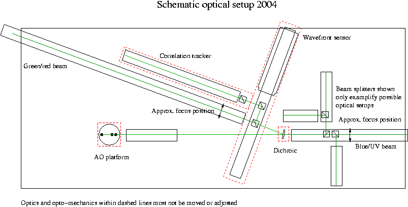
Fig 1. Optical setup 2004
The observer is free to:
- Add or remove optical tracks, optics, beam splitters and CCD cameras in the entire area behind the dichroic beamsplitter, where the main optical track is marked "blue/UV beam".
- Add or remove optical tracks, optics, beam splitters and CCD cameras along the long optical track marked "green/red beam".
Aligning optical tracks
Before mounting any optics, CCD's etc., the optical track should be aligned with respect to the optical axis of the telescope. This is most easily done using a pinhole at primary focus. The AO pinhole is very small and gives too little light, use the other (unmarked) pinhole, shown in Fig. 2. This pinhole will be re-imaged close to the focal plane as a small dot that is of course excellent for alignment. However, far away from focal planes, the pinhole works as a pinhole camera, re-imaging the telescope pupil (i.e 1-meter telescope lens via the adaptive mirror. Because of the small diameter of the pinhole, this gives you a sharp and well-defined pupil image nearly everywhere. Thus the optical axis is well defined by the sunlight from that pinhole.Simply use the Alignment target, marked as such and shown in Fig. 2. This centers itself on the optical tracks and has its center 127 mm above the optical table, which is the nominal height of the optical axis. Proceed as follows:
Choose an optical track that is longer than you actually need, since this simplifies its alignment. Use two L-shaped clamps (see Fig. 2) with short M6 screws to iteratively align the front and back of the track by looking at the image from the pinhole and centering it on the target in the horizontal direction. Use two bars (see Fig. 2) to fix the optical tracks near its endpoints but away from the optics or camera you want to mount. Make sure to tighten the screws pressing the bar alternating between the screws, such that the track remains flat on the optical table.
Aligning CCD Cameras
For centering a CCD camera on the optical axis, focus it roughly on the same large pinhole as used for aligning the optical track. Then adjust the camera horizontally and vertically such that the pinhole is right at the center of its field of view (this should correspond to the cross-hair superimposed on the displayed image. Tighten any screws holding the camera on its holder, since shutter movement induces vibrations. By using the large pinhole, you can now easily co-align all CCD's. For focusing the cameras, see separate instructions.
Aligning Lenses
On the green/red optical track shown in Fig.1., filters for H-a, 630.2 nm (with the SOUP filter) or for the TiO band at 705.7 nm are frequently used. At these longer wavelengths, 0.04 arcsec per pixel corresponds to excessive oversampling and de-magnification of about 2/3:rd times can be used to increase the FOV without loss of spatial resolution. Such de-magnification can e.g be done with a 600 mm collimator and a 400 mm re-imaging lens.
To maintain image quality, the optical axis of a lens must be a) centered on the optical axis (the lens must be at the correct height and at the center of the optical track horizontally) and b) the lins rotated and tilted such that its optical axis is parallell to the optical axis of the telescope. This is most easily done with a laser.
First check the alignment of the laser (in case it has been bumped). Put it on a long optical track (more than one meter), not necessarily on the imaging table. Place first the alignment target very close to the laser and check that the laser spot is precisely at the center of the target. If not, use the three adjustment screws of the laser closest to the target. Then place the alignment target as far away as possible from the laser and adjust the tilt angle of the laser with the second set of alignment screws such that the laser spot is precisely centered on the target. Tighten all alignment screws symmetrically and verify that the laser is still aligned.
Having done this, the laser now is a good substitute for the optical axis of the telescope, assuming that the optical track on which you mount your lens is well aligned (see section on aligning optical tracks).
First, place the target as far away as possible from the lens. Check again that the laser hits the center of the target. Then place the lens such that it is approximately two times further away from the target than from the laser. Now adjust the centering of the lens in x and y such that the laser hits the target while the reflections from the lens go straight back to the center of the laser. When this is the case, the beam going straight through the lens and hitting the center of the target shows that the laser beam goes through the center of the lens. The reflected beam, now at the center of the lens and going back exactly to the center of the laser, shows that the rotation and tilt of the lens is such that its optical axis is aligned with the laser, i.e the optical axis of the telescope.
This procedure does not work with the large pinhole because the reflected light from the lens is too weak and the beam diverging.
How to produce a collimated beam and re-imaging with de-magnification
All re-imaging lenses available at the SST, except the re-imaging lens on the AO platform, are made for re-imaging from or two infinity. Using a single such lens to demagnify the image, produces spherical aberration. With the high F-ratio of our telescope (F48), it is possible that for many of our lenses, the amount of spherical aberration is negligibly small. But deciding this requires ray-tracing of the lenses for the particular de-magnification planned, which has not yet been done. For de-magnifying the image, we therefore always use two lenses of different focal length such that the first lens, referred to as collimator, re-images the image to infinity. A second lens then re-images that image (at infinity) to a final focal plane.
In order to produce a collimated beam after the focal plane, it is best to again use the large pinhole. Find out where the focal plane is by checking with the alignment target. Rig up a the Focusing target, marked as such and shown in Fig.2, which has a cross-hair on a transparent glass with a paper taped to the side of it, such that the cross-hair is at the focal plane. Identify which side of the lens or holder that has an infinity mark, which is the side that should be in the direction away from the telescope (i.e. in the direction of the collimated beam). If the lens has no such mark, then the side with the strongest curvature can safely be assumed to correspond to the side of infinite optical conjugate (the side for which the beam is collimated). Note: If you use the wrong orientation of the lenses, you will introduce spherical aberration into your optical setup.
Place the lens (correctly aligned, see the previous section, and correctly oriented) at a distance from the focal plane which is approximately equal to its focal length. Place the mounted Auto-collimation mirror, marked as such and shown in Fig. 2 behind the lens such that the light is reflected back towards the focusing target. Rotate it at a small angle with respect to the optical axis such that the image of the cross-hair is on the white paper taped close to that target. Move the lens along the optical track until the cross-hair appears well focused on the paper. The beam is now collimated.
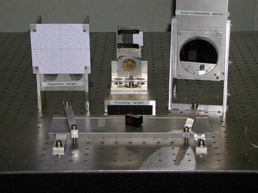
Fig 2. Optical targets used when focusing and aligning
Since the beam is collimated, a re-imaging lens can now be placed at any distance from the collimating lens without changing the final image scale. That lens must have its infinite conjugate mark in the direction of the first lens. The demagnification is given by the ratio of the focal lengths of the re-imaging to the collimating lens. If you need a telecentric image (meaning that the telescope pupil is re-imaged at infinity) at the final focal plane, then the separation of the two lenses must be equal to the sum of their focal lengths. For many applications, putting the second lens close to the first lens will be adequate.
For focusing, place the CCD at the final focal plane, re-insert the large pinhole and make a rough first rough focusing by watching the live image on the screen. For accurate focusing, follow the instructions in the separate manual. However, note that if you use demagnification optics, then the depth of focus (focus tolerance) is reduced by the square of the demagnification. For 2/3:rd demagnification, the depth of focus will be less than 1 mm and the focus of the CCD should be correct to within half a mm, which is difficult to achieve by moving the camera. In order to accurately focus the CCD, it is then much better to focus by moving the collimating (not re-imaging!) lens which gives tolerances for focusing that are identical to those for a CCD without re-imaging optics.
In the particular case of the correlation tracker, we use a 400 mm collimator and a 50 mm re-imaging lens that de-magnifies the image 8x. For this setup, the pupil image formed by the 400 mm lens is close to the 50 mm re-imaging lens in order to allow a large unvignetted field-of view with the small diameter of the 50 mm lens. Here, the focal depth of the image is vanishingly small and the 400 mm collimator must be used for focusing.
Note about screws: The imaging and spectrograph optical tables use M6 metric screws. There is a large number of opto-mechanical components made by Lockheed-Martin that uses U.S 1/4 inch threaded screws that have diameters very close to the M6 screws. Be careful to use the correct type of screws for mounting or assembling opto-mechanics. Also beware that the screwdrivers used to tighten the M6 and 1/4 inch screws are different.
Time-stamp: <2004-03-28 23:25:22 dettori>
Peter Dettori < dettori@astro.su.se >